
This legacy article featured in the first aviation adverts series on my .com domain. It’s neither comprehensive nor recently revised, but visitors to aviation museums might enjoy identifying seemingly anonymous looking nuts, bolts and screws etc fitted to the exhibits.
Aircraft Supplies Co 1917
A search for AGS in the Aviation Ancestry database will return many hundreds of records and will be the subject of an article or two here in due course.
Introduction:
Aircraft general standard (A.G.S.) parts are small items such as bolts, nuts, rivets, fork joints, taper pins, common to all types of aircraft. They are made in a range of sizes, and, as similar parts are made of different materials, a distinguishing system of identification is in use. Special parts made for specific aircraft have no marking to indicate size or material, but are marked with a part number.
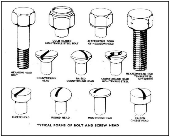
Bolts And Screws:
B.S.F. or U.N. F. threads are used on all standard bolts of 1/4in. dia. and over ; No. 2, 4 and 6 B.A. or U.N.F. are used for smaller sizes. The bolt type is indicated by the shape of the head and each type is made in various lengths and diameters ; the dimensions of the head and the length of the thread are standardised for each diameter of bolt.
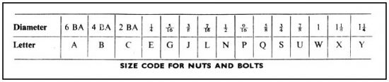
Information such as material, thread diameter, length of the plain unthreaded portion, whether the thread is left- or right-hand and whether the bolt is corrosion resistant is marked on the carton label and may be stamped on the bolt head. This information is abbreviated and in the form of a part number consisting of two to five letters and figures which are related to a size code.
Hexagon-headed Steel Bolts.
These bolts of 1/4 in. dia. and over are stamped with the part number, such as 14G; the number equals the length of the plain unthreaded portion of the shank in tenths of an inch, that is 1·4 in. and the letter “G” indicates that the thread diameter is 5/16 in. (see size code). Vee grooves cut into the head at right-angles to the bolt axis indicates that the bolt is made of high tensile steel. If the bolt is corrosion resistant, that is high tensile stainless steel, the part number is prefixed by the letter ” Z” (Z14G), Bolts with left-hand threads have an additional suffix letter “L” after the part number.
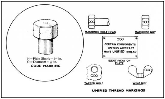
Close tolerance bolts, which are made of high tensile steel, are marked with grooves cut in the head and have a raised disc on the head. Coldheaded bolts are either marked with an embossed ring on the head, or, if a UNF bolt, with a shallow depression in the centre of the head , equal to the shank diameter. To indicate a Unified screw thread, a symbol consisting of two or three circles is marked on the part, carton label or aircraft containing this type of thread . Unless otherwise stated, a replacement bolt and nut must be of the same size, type and material as the original bolt and nut.
Notes.
1. A washer face under a bolt head is not provided for identification purposes, but is the result of using a particular machine in the manufacture of the bolt.
2. Bolts and nuts may be either machined or cold formed but, irrespective of the method of manufacture, bolts or nuts of identical material, type, thread and size are interchangeable.
3. When in doubt as to the identification of new bolts and nuts, reference should be made to the label on the carton in which the bolts or nuts were contained.
4. The use of mild steel bolts in aircraft construction has been discontinued, but a range of bolts in this material and in brass is available for use in aircraft ancillary equipment.
Hexagon-headed Aluminium Alloy Bolts . . All sizes of aluminium alloy bolts of older stock are marked with a letter “L” embossed or stamped on the head to indicate the material. Bolts of 1/4 in. dia. and over are also marked with the part number as described. In later stocks two parallel lines replace the ” L” to indicate the material. Where colour marking is used for identification purposes all aluminium alloy bolts have an anodic film dyed green.
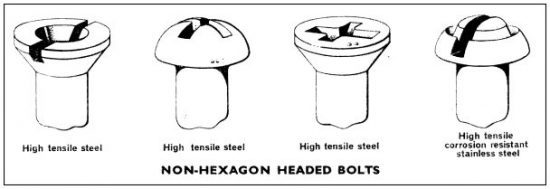
Non-Hexagon-headed Bolts.
These bolts have various types of head which include countersunk, round and mushroom and may have a straight slot or a cruciform recess formed in them. They are not marked to indicate their thread size or length; but those made of high tensile steel may be identified by a countersunk indent in the centre of the head on bolts with a straight slot, and by two raised pips on those with a cruciform recess. Those holts made of high tensile corrosion resistant steel are distinguished by an annular groove in the head.
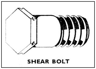
Shear Bolts.
These bolts are made of high tensile steel and are cadmium plated. They may be identified by the thin hexagonal head which is marked with a vee groove to indicate high tensile steel. The marking on the carton label gives the .A.G.S. number followed by a part number consisting of three or four figures. In this number, the number of hundreds indicates the diameter of the bolt in sixteenths of an inch, whilst the other two numbers indicate the length of the plain portion of the bolt in tenths of an inch. that is A.G.S.571 {804 is a shear
bolt of 1/2 in. dia. and 0·4 in. plain length .
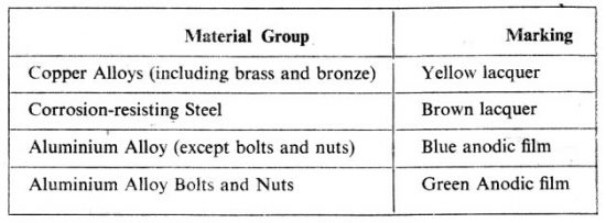
Additional Identification. Small bolts,. in common with other small parts (excluding rivets), which have no recognised standard marking and where the material group cannot be readily identified , are distinctively coloured in accordance with the following colour scheme :-
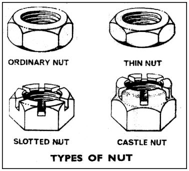
STANDARD NUTS
All standard nuts are hexagonal in shape and are made of similar material to that used for bolts. A nut must be of the same material as the bolt on which it is fitted, with the exception that high tensile steel bolts are fitted with mild steel nuts, unless otherwise stated.
Steel Nuts. All nuts of 3/8 in. dia. and over are marked with their part number on one of the hexagonal faces; the part number is also marked on the label of all cartons containing nuts. Other markings and the size code used for the part number are as described for bolts
Aluminium Alloy Nuts. These nuts are identified by the washer face machined on the base or on both faces of the nut. There is no part number marked on the nut.
Note. All nuts have a 30 deg. chamfer on the edge of the upper face of the hexagon and may be also chamfered on the opposite face. The thin nuts, which are used as locknuts, are always chamfered on the edge of both faces.
Types of nuts continued…
STIFFNUTS
Stiffnuts are provided with means whereby the friction between the threads of the nut and bolt is so increased that the nut may be considered self-locking. Several types of stiffnut have been designed, and the following are standardised for use on aircraft.
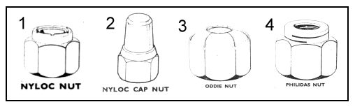
- Nyloc.
This nut is counterbored at the top and spun over to retain a nylon insert. The insert is not threaded initially and has an internal diameter slightly less than the effective diameter of the bolt to which it is fitted. On assembly, the bolt displaces the nylon in forming a thread, and a high friction value is set up between the load-carrying sides of the thread in contact with the nylon. - Nyloc Cap Nut.
Similar action to above, but incorporates a nylon insert in cap form to seal the end of the bolt or screw to which the nut is fitted . The cap nut is used for special applications such as pressurised cabins, fuel and oil tanks, etc., when leakage or seepage along the bolt thread is undesirable. - Oddie.
The top of the nut is counterbored, slotted vertically in three places, and depressed inwards to form a circle of six tongues with a diameter slightly smaller than the bolt core diameter. As the nut is screwed on to the bolt the threads of the bolt displace the tongues upwards, and a load is applied to the contacting thread faces. - Philidas.
This nut is made with a circular crown in which two slots are cut, one above the other, with arc of about 270 degrees. The wings thus formed are de-pitched to provide locking tension.
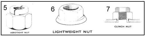
5. Aerotight.
The Mk 1 nut- is made with a circular crown which is slotted across the diameter and also on each side through about 150 degrees, The resultant wings are de-pitched and forced inwards, thus causing a sideways as well as a downwards tension on the bolt threads. The Mk 2 nut has a similar action, but it is slotted on one side only.
6. Lightweight
The top of this nut is distorted to an oval or three-cornered shape. When the nut is screwed on to the bolt, the top of the nut is forced to assume the round shape of the bolt and thus provide a locking device. When the nut is removed from the bolt, it assumes its original shape.
Notes.
1. Care must be taken not ‘ to reject these stiffnuts as unserviceable due to the distortion which is an integral feature of their design.
2. The term “lightweight” is used because this type of stiffnut has equivalent strength of larger nuts with the same thread diameter.
7. Clinch.
This term is used to describe a stiffnut which has a spigot at the bottom of the nut by
means of which it is mounted on its support.
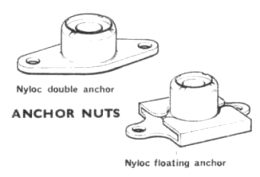
Anchor Nuts.
This term is applied to stiffnuts which are secured to anchor plates. The anchor plates are fixed at the back of a component so that the bolt or screw can be inserted or removed from the front ; two rivets are used to secure the anchor plate to the component.
Notes.
1. If the friction value is so low that the stiffnut on the bolt or screw can be turned with the fingers, the nut is unserviceable and must be renewed.
2. Before renewing a stiffnut, ensure that it is not the bolt or screw thread that is unserviceable.
3. Under no circumstances should a stiffnut be tapped out as this destroys its self-locking properties.
4. When assembled, the end of the bolt should protrude from the nut by a minimum of one thread.
SPLIT PINS
A split pin is a locking device, made of mild steel or nickel alloy, and passes through the slot in the nut and a hole in the bolt or stud. They are normally used with slotted or castle nuts, and must be a good fit in both slot and hole ; the width of the slot determines the diameter of split pin to use. For ease of inspection of airframe split-pinning, the legs of the split pin are opened and bent round the nut.
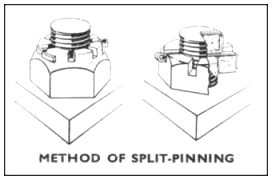
In an aero-engine, to maintain the clearance between moving parts, the legs of the split pin are bent as illustrated. Each pin must be used once only. The size of a split pin is determined by its diameter and length from the underside of the eye to the end of the short leg.
TAB WASHERS
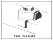
These are thin metal washers with two or more tabs or projections, one of which is bent over the job, or fits into a hole in the job, the other being bent up against a face of the nut. It is not permissible to straighten the tabs and use the washer again: each washer must be used once only.
LOCKING PLATES
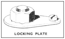
These are thin metal-plates, titled round the nut after it has been tightened. and retained against rotation by a small set-screw. The hole in the plate is usually twelve-sided to allow for close adjustment. Sometimes they are made double-ended to lock two nuts. Locking plates may be used again if they a re a good fit on the nut . The set-screw securing the locking-plate is locked with a spring washer.
LOCKNUTS & WIRE LOCKING
These are screwed down tightly on the ordinary plain nut, or against the part into which a male threaded component fits. They are used on control rod ends or where a rod is screwed into a fitting; they are seldom used as a lock for nuts in aircraft construction.
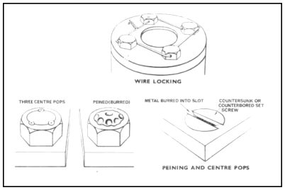
Non-corrodible steel wire is used for locking purposes on aircraft components. The lay of the wire must be such as to resist any tendency of the locked part or parts to unscrew. Wire must be used once only.
Note. When authorised, nuts, bolts, studs, setscrews, etc. , may be locked by peining or centre-punching, but on no account must these methods be used to replace other forms of locking. If, during service, the component requires re-tightening, the locking must be made good afterwards.
CIRCLlPS & TAPER PINS
CIRCLIPS
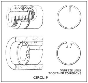
These are made of spring steel and are used to lock round shaped threaded parts. The circular portion of the circlip fits into a groove on one of the threaded parts. and the short bent end enters drilled holes in both threaded parts. thus providing a lock. A circlip may also be used to prevent endwise movement by being sprung into a groove from which it partially projects. Each circlip must be used once only.
Note. All locking devices which are bent in use, such as split pins, circlips, tab washers. and locking wire. must be used once only. To ensure this, such locking devices on removal should be broken or bent to make them useless.
TAPER PINS
Taper pins are used to secure such parts as repair patches, end sockets or plugs to tubes, etc. They a re made of steel or light alloy and are classified by the diameter of the small end and the length. The standard taper used is 1/48
COWLING FASTENERS
Special types of fastener have been designed for use on components such as cowlings, fairings and inspection panels. They hold the component securely in position whilst at the same time allowing for rapid attachment and detachment.
Dzus Fastener.
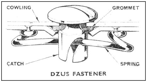
This fastener consists of a catch and a spring. The catch is held in position on the detachable component by a grommet and the spring is riveted to the inner side of the fixed component. A slot in the body of the catch engages with the centre of the
spring, drawing it up when the catch is given a quarter turn in a clockwise direction. The fastener is unlocked by a quarter turn in an anti-clockwise direction.
Amal Fastener.
This type of fastener consists of a body housing a spring loaded click washer ; a cotter, located by slots in the body and centrally threaded to take a locking screw; and a back anchor plate riveted or welded to the inner component. When locked, the body is turned so that the ends of the cotter are positioned between the projecting legs of the back anchor plate, and the locking screw tightened, to hold the parts securely together. The fastener is unlocked by first unscrewing the locking screw about two turns, then. . pressing the locking screw inwards to free the cotter from the legs on the back anchor plate. The body is then turned a quarter turn in an anticlockwise direction to free the fastener.
Note. The locked position of most types of fastener is clearly indicated by the screwdriver slot being in line with short black or white lines painted on the cowling – this is not applicable to Amal fasteners as the slot in the body must align with the painted lines. Because the majority of indicating lines are in one direction, it does not imply that they are the same for all the fasteners on the aircraft. Each fastener
must be carefully examined to ensure that the indicating lines do, in fact, correspond to the position of the slot when the fastener is in the locked position.
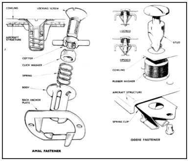
Oddie Fastener.
This comprises a central stud held in position in the outer component by a rubber washer or coil spring, and a two legged spring clip, riveted to the inner component. The stud is bullet shaped and has two recesses near its pointed end. The fastener is locked by positioning the recesses on the stud in line with the spring legs, and pressing the stud with the finger. There must be a definite click as the fastener engages. The fastener is unlocked by turning the stud a quarter turn in either direction, thus turning the recesses out of engagement with the legs of the spring.